
FoosTender is an automatic goalkeeping robot which uses OpenCV, a Raspberry Pi, and a very large stepper motor to stop you from scoring in foosball.
Introduction
In search of a project during our winter break from school, Valentin Astie and I designed and built FoosTender. When deciding what to build, we wanted a system that utilized computer vision and robotic control, and wanted it to be a high performance system. We also wanted the project to be interactive with people. This lead us to the idea of the foosball goaltender. Our design criteria were as follows:
- The goalkeepers reaction time should be fast enough to block any shot from the opponent
- Design it such that no permanent modifications to the table are needed
- Make the system fully integrated, needing only a single power cord, and no laptop/desktop connections
Initial Design Phase
It was calculated that we wanted at least 10 frames of view of the ball approaching the goal for the worst case fastest shot, and thus we needed a camera that could record at ~240 fps. We initially chose a cheap webcam advertised as 640x480 260fps (something we would quickly come to regret). Below is a slow-mo video of a very fast shot.
-
Use the Raspberry Pi 4B as the main controller and vision processor, as handling footage at 240 FPS requires far more processing than any smaller microcontroller can handle, yet we wanted the system to be fully integrated and not require a desktop/laptop to run.
-
The bar with players weighted about 1.5 Kg, thus in order to accelerate and decelerate fast enough to block the most difficult shots, a very powerful stepper was required. A large, 48v 1/2 horsepower stepper motor and driver chosen for accuracy and strength
-
We designed the robot with the intention that it would not permanently alter anything about the foosball table. Clamps and form-fitting 3d prints were the main attachment methods.
We designed in OnShape, allowing for easy collaboration
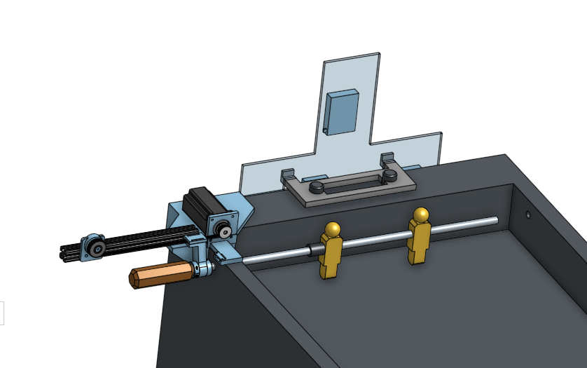 Shown above is the CAD of the robot from a front view. A 3d printed mounting bracket is clamped onto the table, and then aluminum extrusion and the stepper motor are mounted onto the bracket. A belt spans the length of the aluminum extrusion, and terminates on another 3d printed part which clamps onto the foosball table rod.
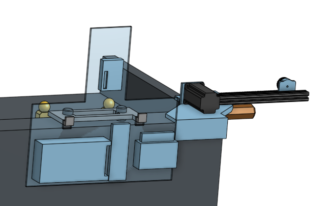
Here is the rear view of the CAD. A 3d printed bracket perfectly slides over the scorekeeping mechanism, and a sheet of Lexan is hung off of the bracket. The power supply, breadboard, stepper driver, and raspberry pi are all mounted to the lexan sheet.
Vision and Detection
Write about how we implemented vision, show pictures and examples, and talk about challenges and successes
- Lighting. The computer vision was significantly affected by time of day, indoor lights, and more. We designed a “mask scanner” to find the best color settings which worked in most lighting conditions. We also used computer techniques such as Gaussian blurs to reduce variability.
-
Camera woes. The initial camera we purchased was old and terribly documented. Driver and software support was almost nonexistent, and getting it to play happily with linux was especially difficult. We quickly sent that camera back and opted for a Raspberry Pi Cam.
-
Raspi Cam Issues. The initial camera we purchased was faulty and would not function. The next camera we purchased functioned, but the software support was not nearly as thorough as expected. There were enormous issues with older software that no longer functioned, particularly with the new OS update that Raspberry Pi put out lately. These emphasized some of the woes of releasing open source software where keeping libraries functional and up to date is not profit driven but instead just from peoples goodwill.
-
Image mapping. Due to camera woes and limited software, an intense crop was necessary to achieve a high framerate. This meant that the camera needed to be mounted far above and behind the table. This meant that camera location became somewhat variable. Contours were analyzed to find the bottom bar, which is of known length. Using linear algebra and scaling methods, the ball’s pixel position can be mapped to a distance and passed to the servo.
-
Processing speeds. The Raspberry Pi 4 remains a micro-computer with little processing power. Initial algorithms were computationally heavy, resulting in very delayed tracking as seen below. We also tested to find the optimal shutter config and pulled from the “lores” (low-res) channel.
Stepper Control
In order to control the stepper motor a direction pin is set high or low, and then pulses are sent to the "step" pin in order to make it move. Each pulse moves the shaft of the motor an amount determined by the microstep setting chosen with switches on the stepper driver. The speed of the motor is determined by the frequency of the pulses sent to the controller.
In order to send high frequency, consistent pulse trains particularly without a bunch of computational OS overhead, we used a library called pigpio. Pigpio uses a daemon in the background which controlls certain PWM pins in various more precise ways.
When sending a predefined motion pattern, much like how you would control a 3D printer, the stepper control worked flawlessly. It was very smooth, and relatively easy to program acceleration and deceleration curves to hit high speeds in a controlled manner. However, the key word here is "predefined". Creating a foosball goalie inharently makes each motion not predefined, and the desired target locaiton updates 240 times a second. Once you have sent a set of pulses to the pigpio daemon, you can not cancel the wave without losing track of where the stepper is positioned. This means you must send very small waves, and constantly see which direction the waves must travel. This video shows the jerky step based motion of the player trying to follow the ball.
This issue above turned out to be the biggest fundamental flaw, and was the thing that holds this project back from true success at the moment. It became clear after many hours attempting different control mechanisms with the stepper motor, that it is impossible to get smooth, accurate, rapidly updating positional tracking. The correct tool for the job is a DC motor with an encoder, and a positional PID tracking the location of the ball. With more time, or next time we return to the project, this will be the proper solution. This particular aspect was difficult, frustrating, and a learning experience that will not be forgotten.
Final Result
-
OpenCV images. Final video of maching functioning.
Future Improvements
-
Running a stepper control algorithm with a fleshed out set of control functions on a micro controller would be far more effective. Likely even better would be ditching the stepper as a concept, and instead using a large DC motor and encoder, and tuning a PID position controlled loop to automatically handle acceleration, and allow for rapid parameter tuning.
-
Better implementation of multi-threading. Tests indicate that the python library was not “multi-threading” as we expected. This issue would likely be fixed with the use of ROS.
-
Torsional spring system to return the keeper into a vertical position after perturbation. A button to disable the servo is also needed, so that the user can operate the goalkeeper as normal.
-
Utilizing an available robotics software suite such as ROS would be a far better use of time, resulting in better performance for less effort.
-
Designing the system to not modify the table was a fun challenge, and very feasible especially if more time was given. However in order to build the best robot in a limited time, table modification would be essential and allow the robot to look and perform far better.